Product Details:
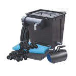
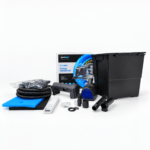
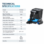
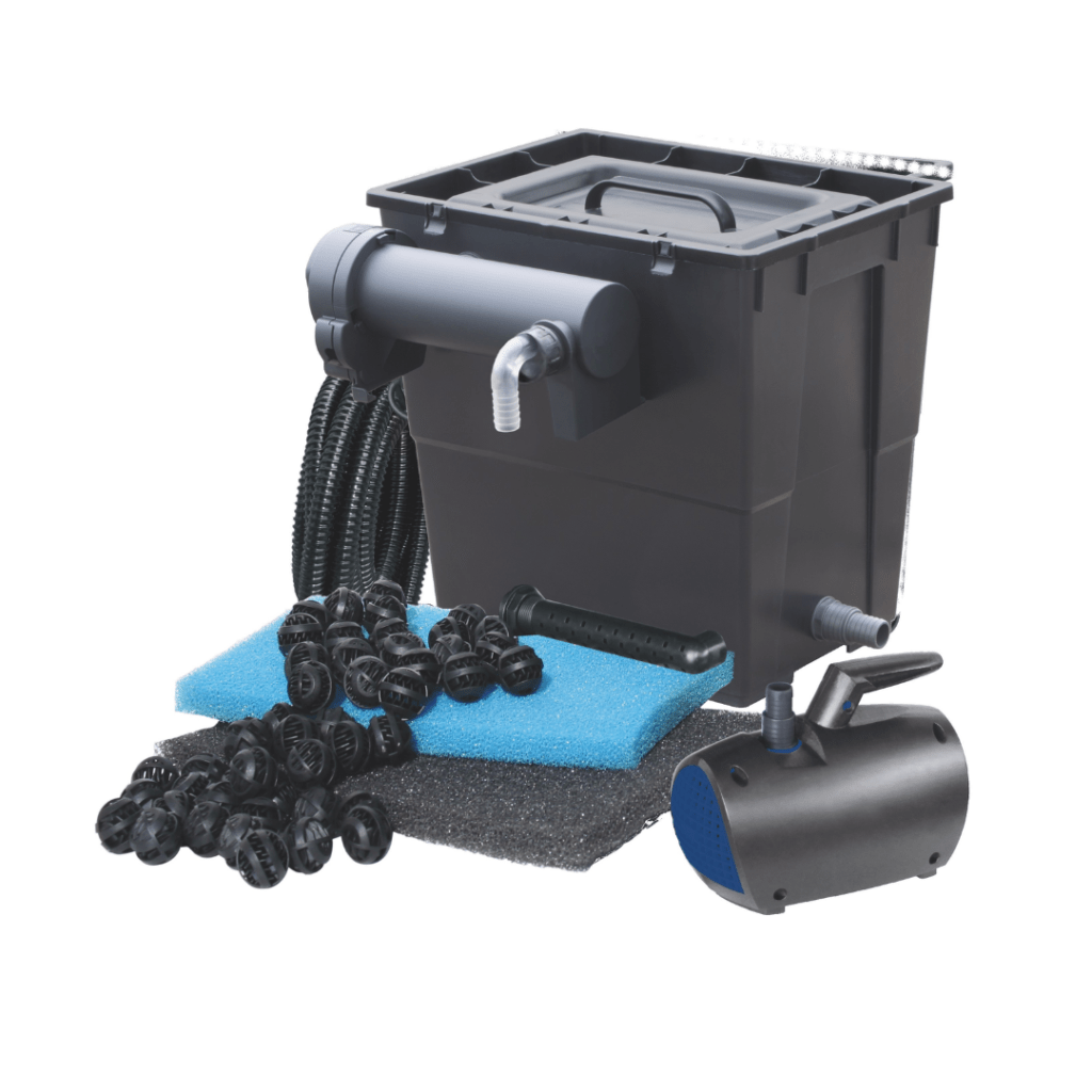
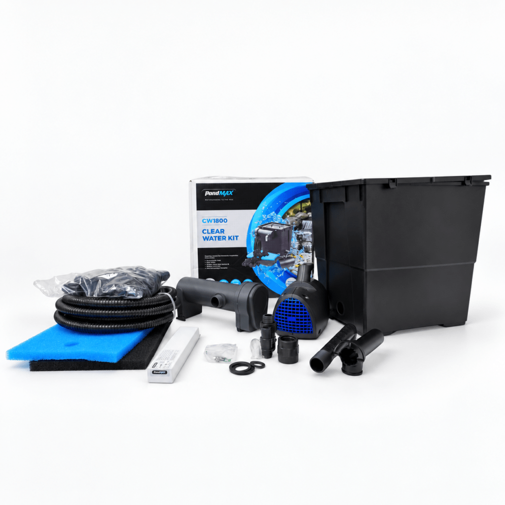
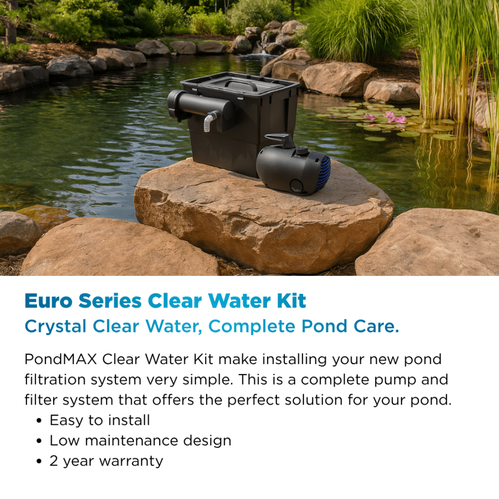
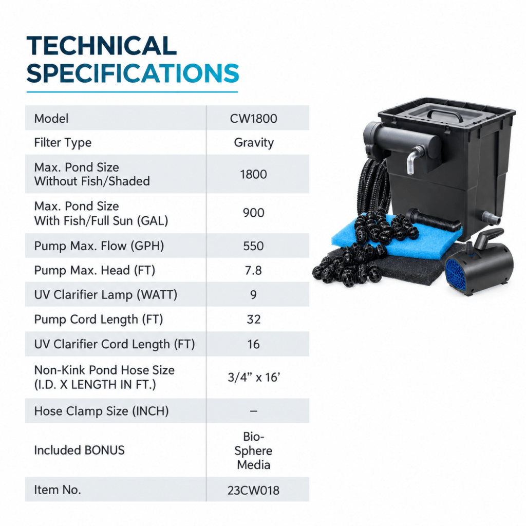
PondMAX CW1800 Clear Water Kit is a complete pond filtration kit that combines the CW1800 flow-through filter tank, PondMAX FP550 Pump, PondMAX UVC9W Water Clarifier, filtering materials, kink-free hose, and fitting accessories in one matched system. It is rated for ponds up to 1,800 gal. (7,000 L) without fish/shaded and 900 gal. (3,500 L) with fish/full sun. This pond pump and filter kit provides a practical filtration setup for garden ponds within the recommended sizing limits.
FEATURES
Easy-to-install, low-maintenance design for DIY pond owners, no guesswork when sizing the pump or filter
Promotes clear water and a healthier environment for fish and aquatic life
Ideal for a wide range of garden ponds, koi ponds, and water features
Multi-stage filtration with dual-action bio sponges, low-maintenance backwash cleaning, and built-in cleaning and UV indicators.
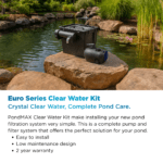
PondMAX CW1800 Clear Water Kit is a complete pond filtration system that combines water circulation, UV clarification, and flow-through filtration in one pond filter kit.
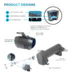
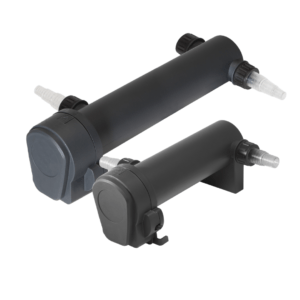
The included PondMAX FP550 Pump moves water from the pond through the kink-free hose to the PondMAX UVC9W Water Clarifier, which is installed on the CW1800 filter tank. The UVC9W Water Clarifier provides the UV clarification stage used by the Clear Water Kit to help address green water and must not be immersed into water or operated dry.
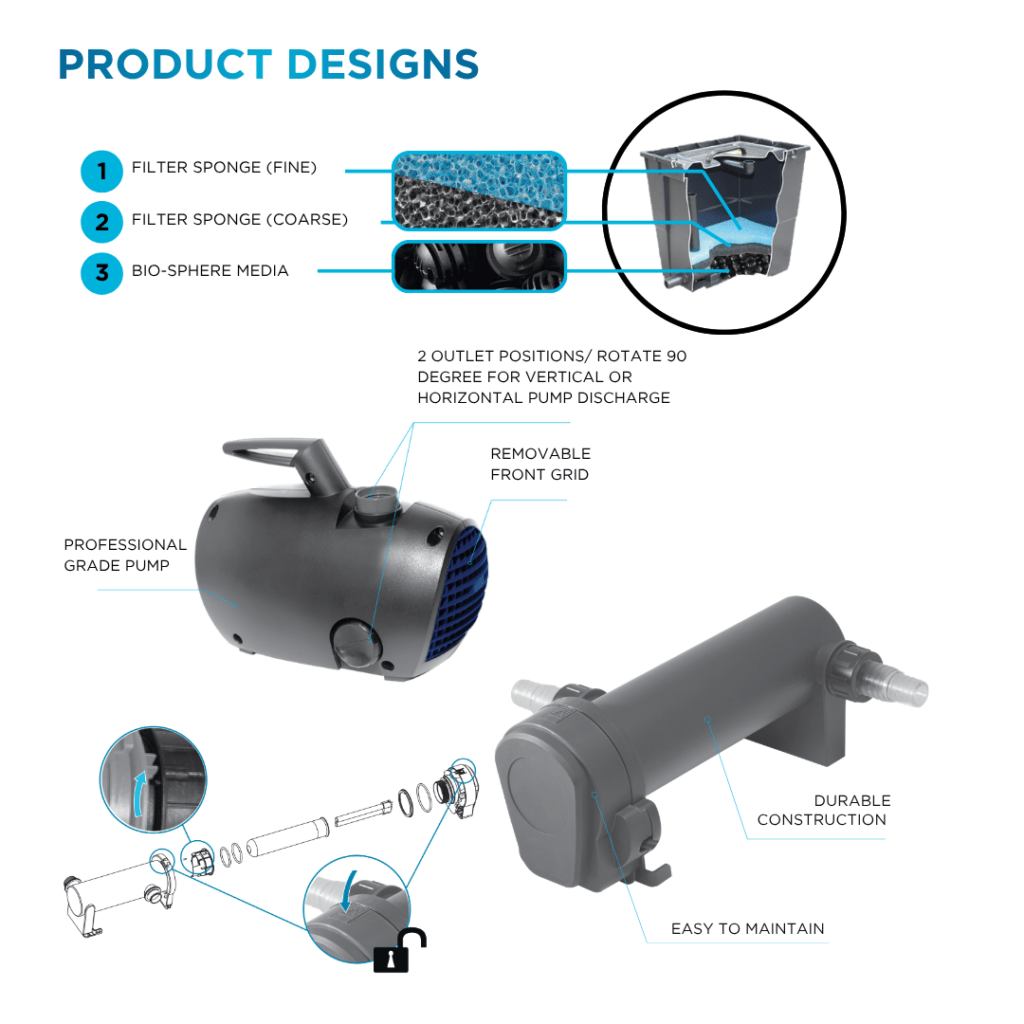
Inside the CW1800 filter tank, the filtering materials are installed according to the instruction manual: Bio-sphere media on the tank bottom, coarse sponge (black), then fine sponge (blue). Water enters the filter tank through the spray bar and returns to the pond through the overflow pipe and connected kink-free hose.
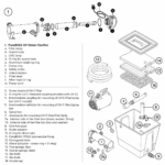
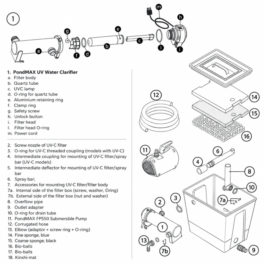
The kit includes the filter tank and lid, fine and coarse filter sponges, Bio-sphere media, spray bar, overflow pipe, PondMAX FP550 Pump, PondMAX UVC9W Water Clarifier, 16 ft (5 m) kink-free hose, hose barbs, and fitting accessories. The CW1800 is rated up to 1,800 gal. (7,000 L) without fish/shaded and 900 gal. (3,500 L) with fish/full sun.
How it works
1. PondMAX FP550 Pump moves pond water through the kink-free hose to the PondMAX UVC9W Water Clarifier.
2. PondMAX UVC9W Water Clarifier is installed on the PondMAX CW1800 Clear Water Kit tank and connects to the spray bar. It provides the UV clarification stage used by the pond filter system to help address green water.
3. The spray bar distributes water into the CW1800 filter tank. The filtering materials are installed from the tank bottom in this order: Bio-sphere media, coarse sponge (black), fine sponge (blue).
4. Water returns to the pond through the overflow pipe and connected kink-free hose.
Placement and operating requirements
- PondMAX CW1800 Clear Water Kit and PondMAX UVC9W Water Clarifier must not be immersed into water.
- PondMAX UVC9W Water Clarifier cannot run dry, but must be connected to a pump.
- It is recommended to place the PondMAX UVC9W Water Clarifier at the minimum distance of 6.5ft (2m) from the pond edge
- Proper functioning of the PondMAX UVC9W Water Clarifier is demonstrated by blue light on the transparent adaptor.
Laying of Filtering Materials
- Unpack the bio-sphere media from the package and place on the tank bottom, distributing them uniformly.
- Place the sponges inside the filter box, so that their hole is located on the overflow pipe. For this purpose, act in the following order: coarse sponge, black, fine sponge, blue.
- Close the box with the cover.
Pump use and shut-down
- PondMAX FP550 Pump can operate both immersed into the pond and outside the pond, provided that it is located in the ground lower than the water level in the pond and connected with it.
- First switch the pump off and then the PondMAX UVC9W Water Clarifier, disconnecting the power cord plug from the socket.
Tank Filter Cleaning
It is necessary to periodically inspect the interior of the box and, if necessary, clean the filter materials under running water to eliminate residue and grime that have accumulated. Do not use chemical detergents.
- Open PondMAX CW1800 Clear Water Kit filter tank.
- Take out the filtering materials and clean them, using only cold running water to prevent harm to microorganisms providing biological filtration.
- Clean the internal compartment of the filter tank with a jet of water.
- Put the filtering materials back in the filter tank, following instruction in LAYING OF FILTERING MATERIALS, depending on the filter model.
To ensure optimum performance of the filter, it is recommended to replace the lamp in PondMAX UVC9W Water Clarifier every 5000-6000 hours, which corresponds to utilization inside pond for one season.
Not sure what fits? Try Search or visit
Support for setup guides.
Need parts? Check the Parts category
for replacements that match your model.
Reviews
There are no reviews yet.